New Antenna System – pt 2, What?

See https://wp.me/p4spp6-ih for part 1

Garden Plan

I started off by seeing how I could get the best from using the fibreglass mast in the middle of the back fence. Unfortunately, the internal angle would be too small for a dipole erected in a horizontal Vee, so that left me with 13m to play with. Not much.

I could put a 30m dipole in (with the ends drooped) and could then have 20, 17, 15, 12 and 10m dipoles in a fan; but this would be a nightmare to set up, and the weight would probably be too much for the fibreglass mast . Also, conditions are still declining IMO, so I really want 40m (at least).

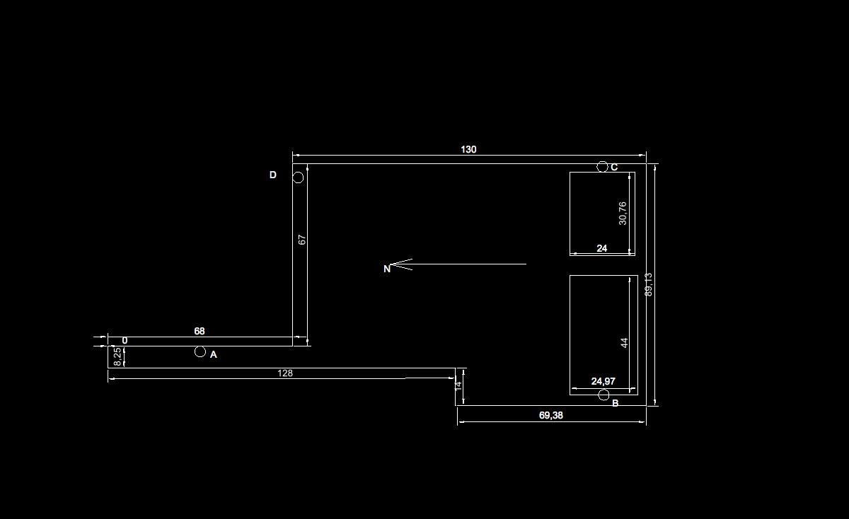
Luckily, a change in the garden provided me with more options. We’ve just put in a new shed in the bottom SE corner of the garden, and this gave me the idea of mounting a pole on the end of the shack (B on the plan) and another on the end of the shed (C on the plan). Add in a stub mast on the gable end (A) and I now have 36m to play with (albeit in an odd shape). Plus, the middle is roughly above the shack (see plan).

80m Doublet

This led me to the antenna I am actually building: an 80m doublet (with one drooped end) fed with ladderline from the shack. One side runs in a straight line from the gable end (A) to the shack (B). The other runs at right angles to the shed (C) and then back to the house (D). I’m going to model this to see if there are any reasons not to follow this path, but it looks good.

Tuner

The problem of course is that I really need a balanced tuner for this to work. Even without modelling, I foresee that the feedline will be unbalanced because of the odd shape. Putting this straight into an unbalanced tuner would be foolish. However, I do have the SG-230.

What I am doing is to install a 1:1 Guanella (Current) Balun on the end of the ladderline and connect the unbalanced output direct to the SG-230. The Balun should force the ladderline to be balanced and reduce radiation from the ladderline.

Provided the impedance swing is not beyond the capabilities of the SG-230 (and I’ve no clear idea of what those are), this should work. As the tuner will now be “hot” I’m installing an RF Choke on the coax from the tuner to kill any RF that wants to go down the outside of the shield.

The next part will cover building the antenna.

New Antenna System – pt 1, Why?

We moved to the current QTH in 2009. We thought that we’d be here for about 10 years and then move on once I retired. As such, I didn’t take too much notice of the suitability of the QTH for amateur radio. Big mistake. The QTH is in a lovely location, but it’s hemmed in by other properties, it’s down near the River Great Ouse, and has a 20m high ridge running SW-NE behind it.

All of the above makes for a sub-optimal RF environment; mainly due to locally generated noise. On 40m and using my current antenna, I regularly get a noise level of S9+10dB.

We’ve now decided to stay here, so I need to make the best of what I have.

Current Antenna

Garden Plan

The plan of the property (dimensions in cm) shows my shack in the SW corner of a 13 x 8m back garden. There was a convenient concrete washing line post in the middle of the back fence, so up until now I’ve been using a long wire antenna made of Flexweave running in a wonky inverted-L from the shack, to the top of a fibreglass mast lashed to the washing-line post and thence to the back of the house. The Long-Wire is tuned with my trusty SG-230 SmartTuner; which I used at my previous QTH. There are also a set of tuned counterpoises that run around the fence.

It’s not a bad antenna, but it does pick up a lot of noise. It’s also been deteriorating over the last year or so. See later for why.

Options for improvement

As I see it, I have several avenues to pursue.

  1. Replace the current antenna with something better.
  2. If still no improvement, install a dedicated RX-only antenna (e.g. Magnetic Loop such as the Wellbrook https://www.wellbrook.uk.com/loopantennas/Loop_Antennas/ALA1530LN)
  3. As per option 2 but move the RX antenna to a quieter location and operate it remotely.
  4. Move the TX antenna (and K3S) to a quieter location and operate remotely.
  5. Move 🙂
  6. Give Up.

I’m going to start with Option 1.

Potential new antennas

I started off by exploring installation of a beam of some sort on a tower. This would have the advantage of directionality and reduced noise (if only from being higher). The challenge is the limited space. Even if I installed the tower in the middle of the garden, I’d only have 8m diameter to play with. I could get a Hexbeam or a Cobweb in without infringing on neighbouring properties, but nothing bigger.

Even without discussing this with the XYL, I discarded this notion, but did explore mounting a mast on the back of the house. Something like the Tennamast or something from MM0CUG https://www.mm0cug.co.uk/shop/steel-box-section-masts/. This could have worked, but after discussions with neighbours, I realised I would get objections and decided to explore other avenues first.

The alternative is to installed a better wire aerial, and that’s what I’ll cover in the next part.