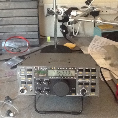
It’s done, the K2 is complete

At least as far as the basic unit anyway.

K2

After getting over the VCO problem, I’ve been able to make steady, if slow, progress towards completion. The filters are only roughly peaked because I don’t have an RF signal generator. I will rectify that later as my next project is to build an RF signal generator controlled by an Arduino.

I still have a number of option modules to build and install: KSB2, KAT, KNB2, KIO2, KBT2 and KDSP2. None are too difficult and I can pick those off at my leisure.


Making progress again

OK, we got past the problem with the VCO.

After tracing through the signals, I checked the levels on DIN and CLK against the indicative levels in the manual. They were the wrong way up!

At this point I got on to the Elecraft mailing list and started asking questions. Luckily, Don Wilhelm W3FPR was on hand to offer some advice. Essentially, the main reason for the VCO not locking was likely to be the values of L3 and T5 being such that the voltage swing on the PLL couldn’t get the VCO to change frequency enough to lock. The advice was to either adjust L3 or change the turns on T5.

I didn’t want to disturb T5 unless it was really necessary, so I did a bit of thinking. The PLL is calibrated when the K2 is switched on for the first time. The MCU swings the VCXO through its full range and measures the relationship between PLL data and VCO frequency. It uses the results to program the EEPROM U3. What if, I reasoned, if the EEPROM calibration had not completed properly? I decided to give the rig a full reset (hold keys 4-5-6 in when switching on).

Bingo! Immediately, the VCO locked on.

Next step was to adjust L3 to set the voltage range so that the VCO works on all bands.

More problems – my fault this time

I had to tweak T5 a bit, but I got the VCO to lock OK on some bands, but not on others.

Turned out that I had put a 47nF capacitor in C74 instead of 47pF. Not much difference!

Anyway, I changed it and all bands work OK.

Lastly, for this evening anyway, I got as far as checking the BFO frequencies.
Debugging the VCO problem on my K2

I’ve been away on business a bit over the past few weeks and have only managed a couple of snatched hours on radio construction. However, I did manage a couple of hours last night to try and find out why the VCO is off frequency.
I started off by seeing how the VCO frequency changed as I adjusted the controls. The main control seems to have no effect at all. I connected my Rigol ‘scope to test point P1 and there was no change as I turned the tuning knob. However, changing bands did affect the frequency. That would seem to rule out the VCO itself as a source of error, for now anyway.
Looking at the circuitry, it seemed that the obvious next place to look was the MC14145170 PLL synthesiser, U4. This takes the VCXO output and compares it with the VCO output to generate a varying control voltage that changes the VCO frequency to keep the VCO locked to the VCXO. U4 changes the frequency in 5kHz steps and interediate frequencies are generated by varying the frequency of the VCXO using a pair of varicaps and a LTC1451 DAC.
Probing around, it immediately became obvious that something is amiss. There should be clock and data signals coming from the microprocessor on the Control Board and going to the DAC and the PLL chip. There isn’t.
The microprocessor is running OK, because the front panel is working and driving AUXBUS to change the VCO is bands.
Clock (SCK) and data (SDO) are created on the Control Board by the PIC U6 and they appear to be dead as well.
Next stage is to work out why the PIC is not generating SCK and SDO, or why the outputs are being held high; which is an alternative explanation.